Manufacturing
The Manufacturing window combines the calculated PCB operations into an ordered CNC job. Here you choose what will be machined, set the execution order, select the coordinate origin and validate the job before generating G-code.
1. Calculate the required operations
Only processes that have already been calculated appear in the Operations list. Prepare the required contouring, drilling, edge-cut, alignment-pin and other operations before building the final sequence.
2. Build the manufacturing sequence
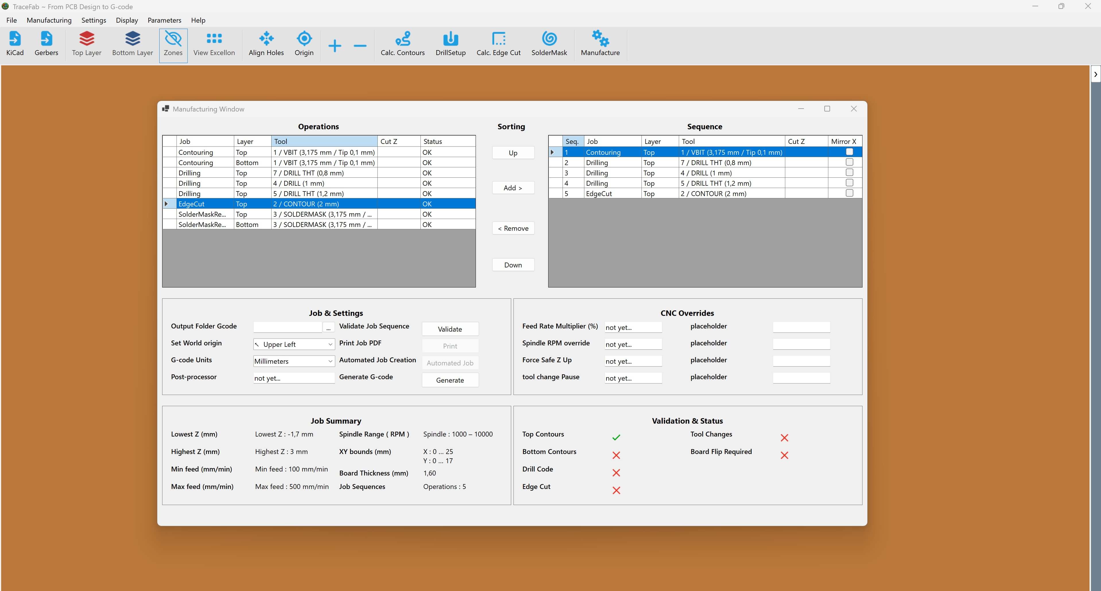
Operations and Sequence
- Operations: every calculated process available for the current PCB.
- Add >: copies the selected operation into the Sequence list.
- Up / Down: changes the machining order.
- < Remove: removes a row from the Sequence without deleting the calculated source operation.
3. Choose a safe machining order
- Create alignment holes before loosening or flipping a double-sided PCB.
- Plan all tool changes and any required Z-zero changes.
- Complete contouring, drilling and similar work before releasing the PCB perimeter.
- Place the final outer Edge Cut near the end of the sequence.
You can create separate NC programs for different stages or PCB sides. After generating one file, remove its rows from the Sequence and assemble the next file; the calculated Operations remain available.
4. Configure the job settings
- Select the output folder and use a descriptive G-code filename.
- Choose the Set World origin position.
- Select the required G-code units.
- Enable Mirror X only for sequence rows that require it.
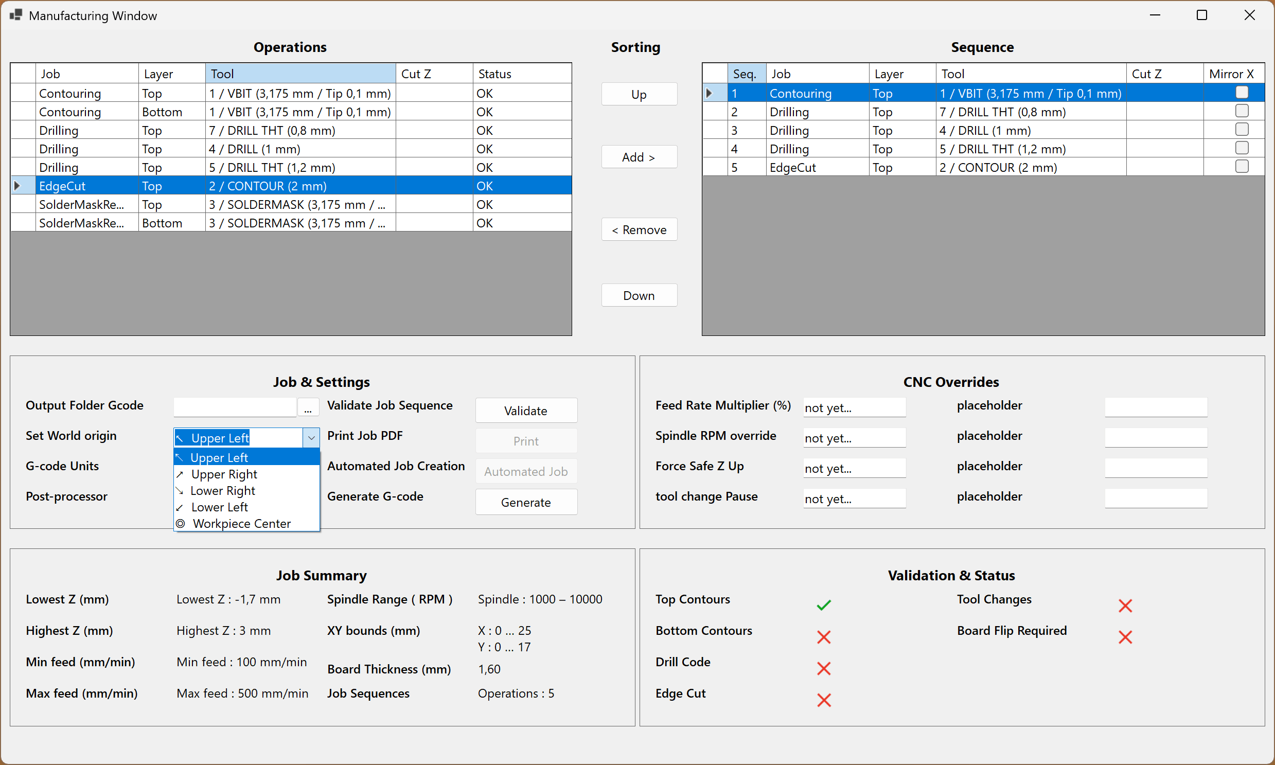
5. Validate the sequence
Select Validate after the Sequence and job settings are complete. Review the Job Summary, including the lowest and highest Z, feed range, spindle range, XY bounds, board thickness and operation count.
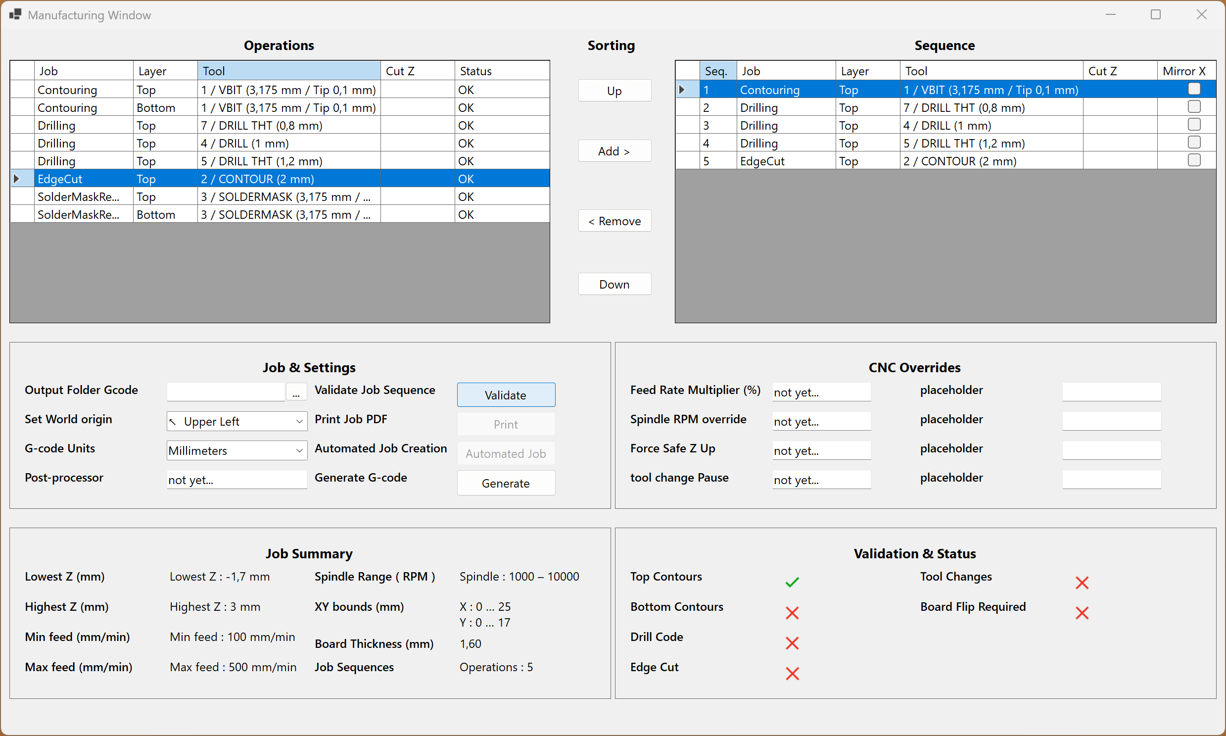
Pre-generation checklist
- All required operations are present exactly once unless repetition is intentional.
- The sequence order matches the real machining and board-flip workflow.
- The outer Edge Cut cannot release the board too early.
- Mirror X is correct for every applicable row.
- The origin, physical CNC zero, units and output location agree.
- The Job Summary values are plausible for the PCB and machine.
6. Generate and inspect the G-code
- Select Generate.
- Choose the final .nc path and filename.
- Confirm that TraceFab generated the operations in the displayed order.
- Inspect the G-code before loading it into the CNC controller.