PCB Edge Cuts
Edge cutting creates the milling paths that separate the finished PCB from the surrounding material. TraceFab can offset the board outline, divide the cut into depth passes and add bridge gaps that hold the PCB in place during machining.
1. Check the board outline
- Confirm that the imported PCB has one valid, closed outer outline.
- Check the board dimensions under File > Board Dimensions.
- Make sure the outline is positioned correctly around the copper and drill data.
- Make sure a suitable cylindrical milling tool is available in the Tool Library.
2. Open the Edge Cut window
- Select Calc. Edge Cut on the toolbar, or open Manufacturing > Calc. Edge Cut.
- Select the cylindrical milling tool that will be installed in the CNC machine.
- Confirm that the physical tool diameter matches its Tool Library entry.
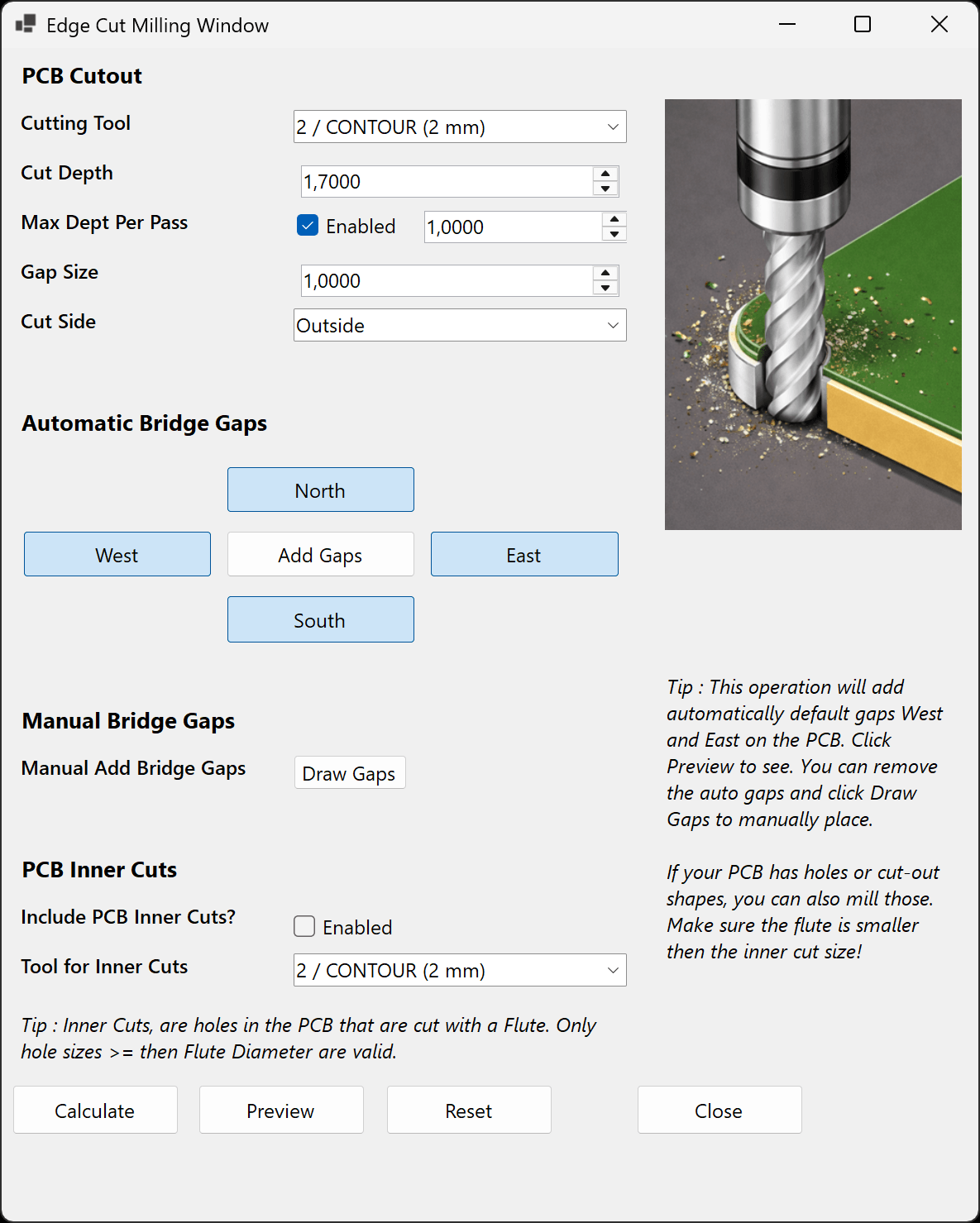
3. Configure the cut
Cut Depth and Max Depth Per Pass
Cut Depth is the final cutting depth. By default, TraceFab uses the PCB thickness plus a small overcut. Enable Max Depth Per Pass to divide the total depth into several passes and reduce the load on the tool.
Cut Side
- Outside: keeps the external PCB dimensions and is the normal choice.
- Center: places the tool centre on the imported outline.
- Inside: moves the path inside the outline and reduces the finished dimensions.
4. Add bridge gaps
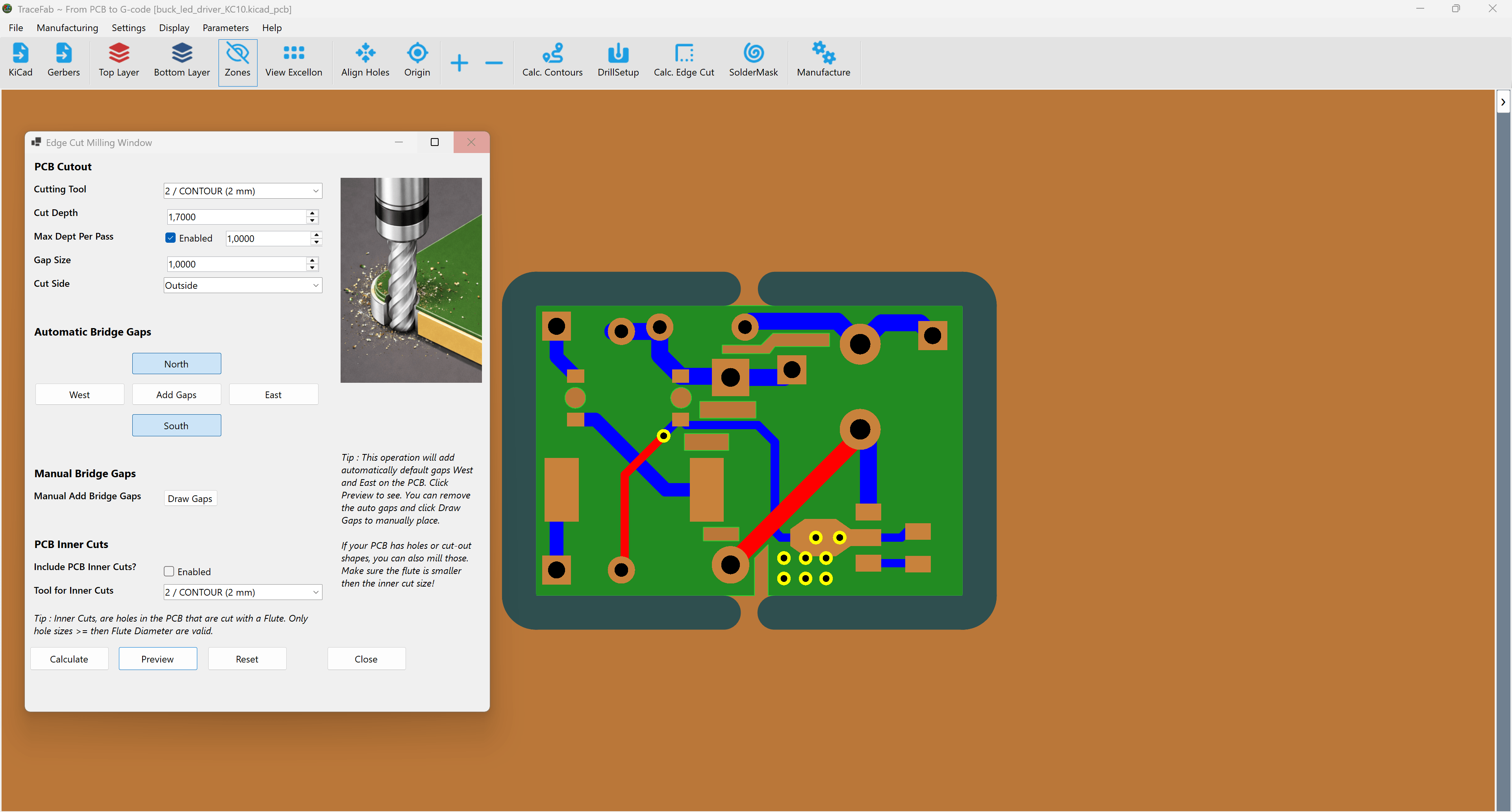
Bridge gaps leave short uncut tabs in the outer path so the PCB remains attached to the stock. Set a suitable Gap Size, choose the required North, East, South and West positions, and select Add Gaps. Select Preview again after changing any gap setting.
Manual gap placement
- Select Reset and clear unwanted automatic gap directions.
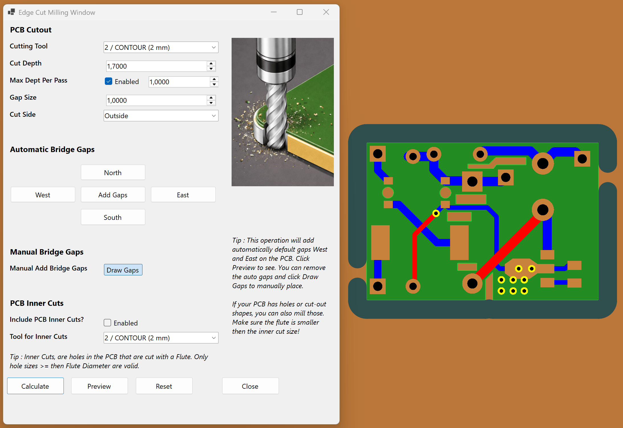
- Select Preview, then Draw Gaps.
- Left-click near the outer edge-cut path to add each gap.
- Disable Draw Gaps when placement is complete.
5. Include inner cuts when required
Enable Include PCB Inner Cuts when the PCB contains internal routed openings. Select a separate cylindrical tool if required. The cutter must physically fit inside every enabled opening.
6. Preview, calculate and review
- Select Preview.
- Check that the outer path is continuous and follows the intended Cut Side.
- Check every bridge gap and optional inner cut.
- Select Calculate when the result is correct.
Review checklist
- The outer path is a complete closed loop.
- The finished dimensions match the selected Cut Side.
- Bridge gaps are visible and strong enough to hold the PCB.
- Every inner cut is visible and the selected tool fits.
- The tool, final depth and depth per pass are correct.