Alignment Pins
Alignment pins provide repeatable reference holes for double-sided PCB milling. TraceFab creates two or four symmetrical pin locations that can be drilled into the PCB and wasteboard before the board is flipped.
1. Prepare the setup
- Secure the wasteboard and PCB so they cannot shift.
- Establish the physical CNC XY origin and Z zero.
- Choose straight, accurately sized alignment pins.
- Test the pin-to-hole fit in scrap material when possible.
2. Select the tool and pin size
- Select Align Holes on the toolbar, or open Manufacturing > Alignment Pins.
- Select a drill or cylindrical milling tool from the Tool Library.
- Set the required pin size and verify the displayed spacing.
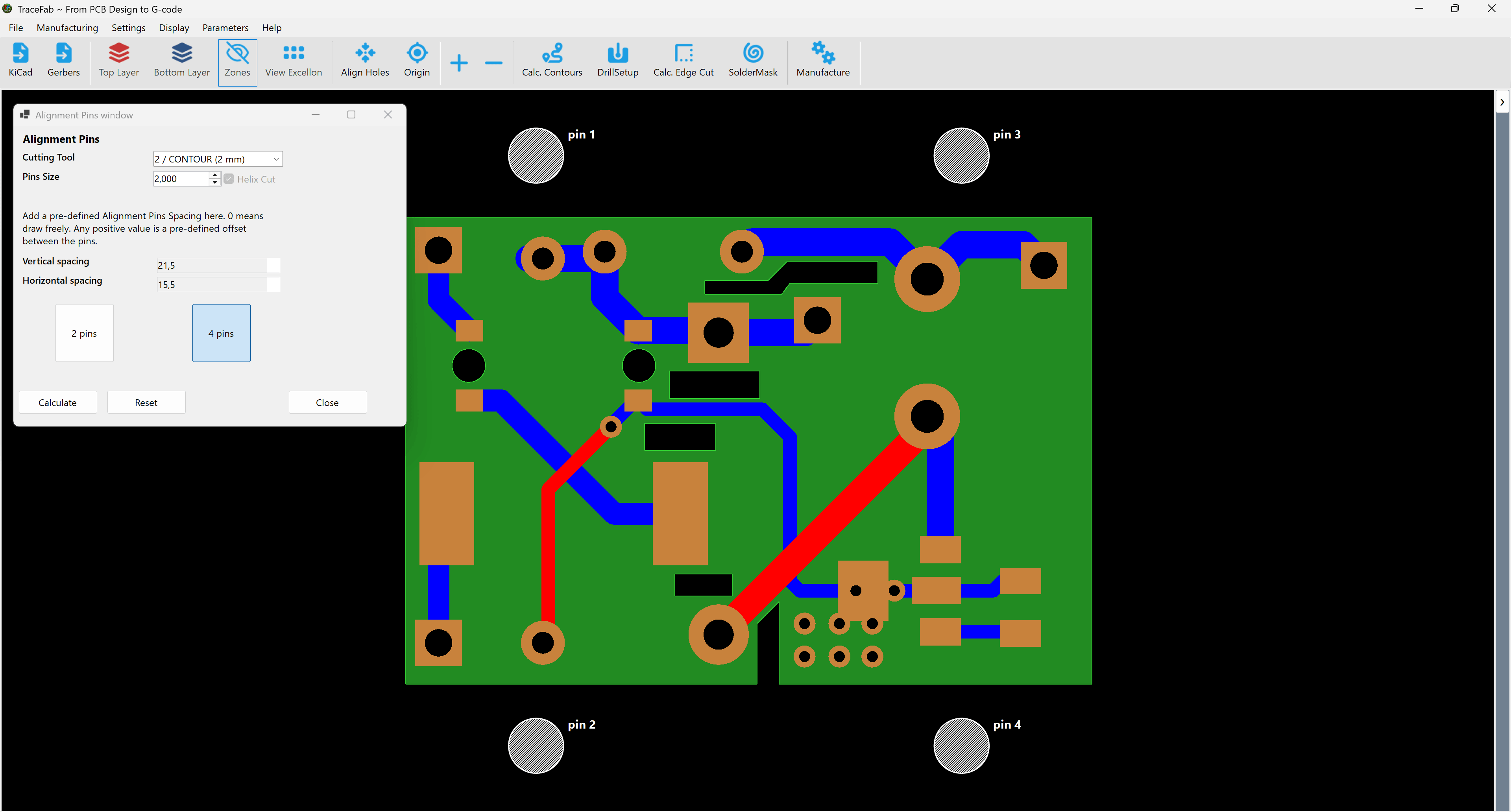
Drill or cylindrical mill
- Drill: creates a direct plunge hole at the drill diameter.
- Cylindrical mill: uses a helical cut to create a larger pin hole.
3. Position two or four pins
Two pins
Select 2 pins, then click the required anchor location in the PCB view. TraceFab places the second pin symmetrically across the horizontal centreline. This is the minimum repeatable setup.
Four pins
Select 4 pins, then click the anchor location. TraceFab mirrors it across both centre axes. Four pins offer more support, but inaccurate holes or pins can cause binding.
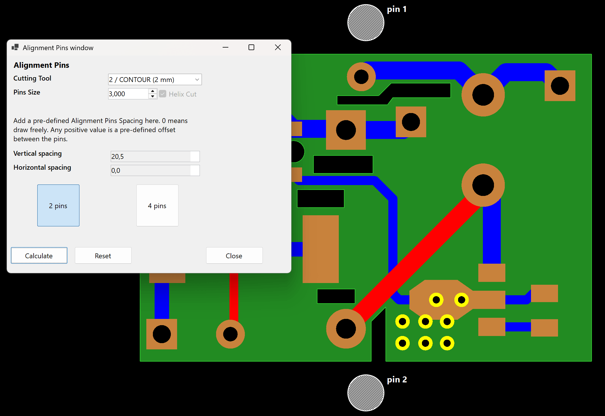
Placement checklist
- Place pins as far apart as the machine and stock safely allow.
- Keep them clear of copper, the PCB edge path and clamps.
- Confirm that every pin location remains inside the wasteboard and machine limits.
- Use Reset before creating a different placement.
4. Calculate the alignment operation
Select Calculate after checking the tool, pin size, depth and placement. TraceFab stores one Alignment Pins operation for use in the Manufacturing window. Recalculate after changing the setup.
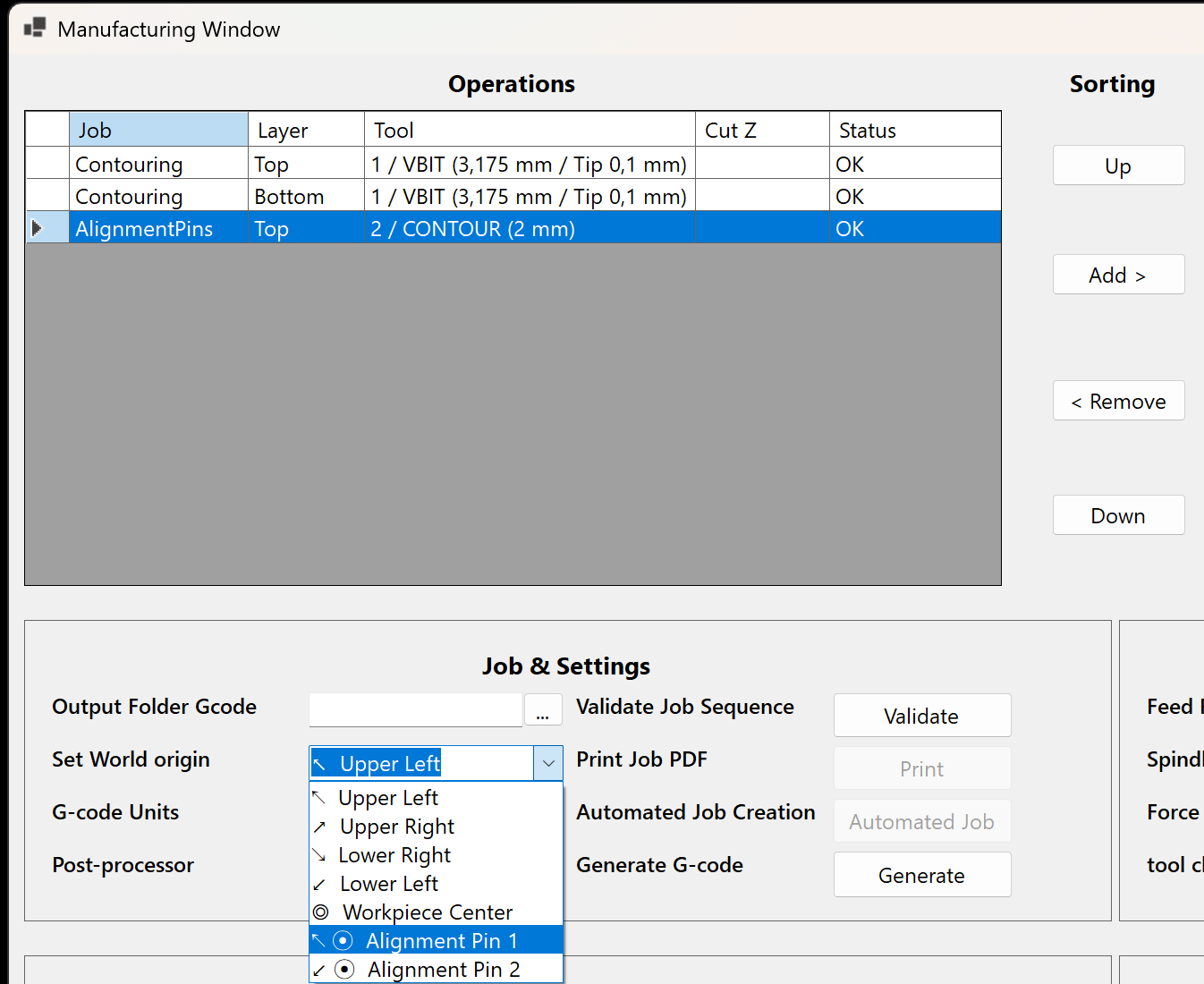
5. Use the same pin as the XY origin
In the Manufacturing window, Set World origin can use one of the numbered alignment pins. Selecting a pin changes the XY coordinates written to the G-code; it does not set the physical work offset on the CNC controller.
6. Follow a controlled board-flip workflow
- Add the Alignment Pins operation before any step that loosens or flips the PCB.
- Machine the pin holes and insert the alignment pins.
- Machine the first PCB side.
- Do not move the wasteboard, pins or CNC origin.
- Flip the PCB in the intended direction, reseat it fully and secure it again.
- Apply Mirror X to the required bottom-side sequence rows.
- Perform a dry run above the PCB before cutting the second side.