Contouring and Isolation Routing
Contouring creates CNC toolpaths around copper tracks, pads, vias and copper areas. Follow these steps to calculate and verify the isolation paths before manufacturing.
1. Check the imported PCB
Before calculating contours:
- Confirm that the PCB dimensions and visible geometry match the source design.
- Check the top and bottom copper layers separately.
- Confirm that pads, tracks, vias and copper zones appear correctly.
- Make sure a suitable contouring tool is available in the Tool Library.
2. Open the Contouring window
- Select Calc. Contours on the main toolbar, or open Manufacturing > Calc. Contours.
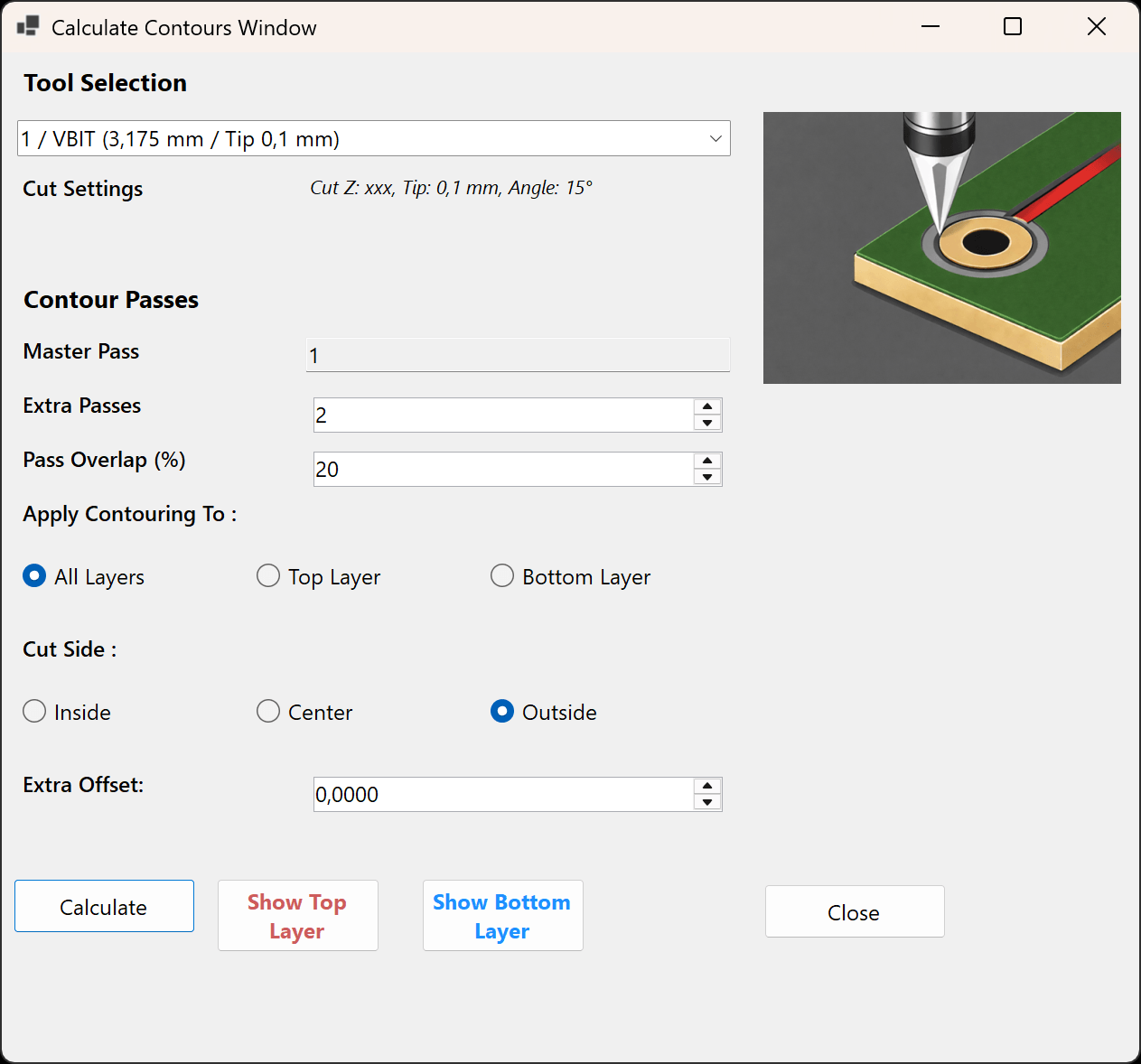
- Select the contouring tool that will be installed in the CNC machine.
- Check the displayed tip size, angle and cutting information.
3. Configure the contour passes
Master Pass
Every calculation contains one mandatory Master Pass around the copper geometry. Its value is fixed at 1.
Extra Passes
Extra Passes add paths beside the Master Pass and widen the cleared isolation channel. Use only as many as the PCB requires because every additional pass removes more copper and increases machining time.
Pass Overlap
Pass Overlap reduces the spacing between adjacent passes. More overlap can prevent thin copper ridges, but also increases repeated cutting and machining time.
4. Choose the layers and toolpath position
Apply Contouring To
- All Layers: calculates both top and bottom contour operations.
- Top Layer: calculates or replaces only the top-side result.
- Bottom Layer: calculates or replaces only the bottom-side result.
Cut Side
- Outside: the normal choice for isolation routing and the default setting.
- Center: places the tool centre on the copper outline.
- Inside: places the tool centre inside the copper feature.
Extra Offset
With Cut Side set to Outside, a positive Extra Offset moves the contour farther away from the imported copper outline. Apply this conservatively and check all narrow clearances.
5. Calculate and review the result
- Select Calculate.
- Wait for TraceFab to update the PCB preview.
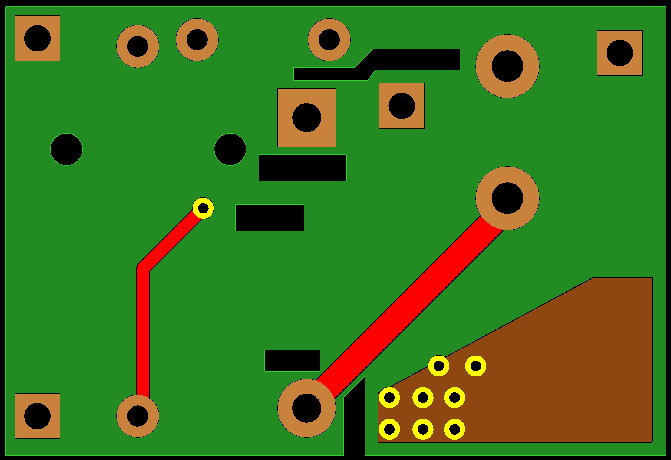
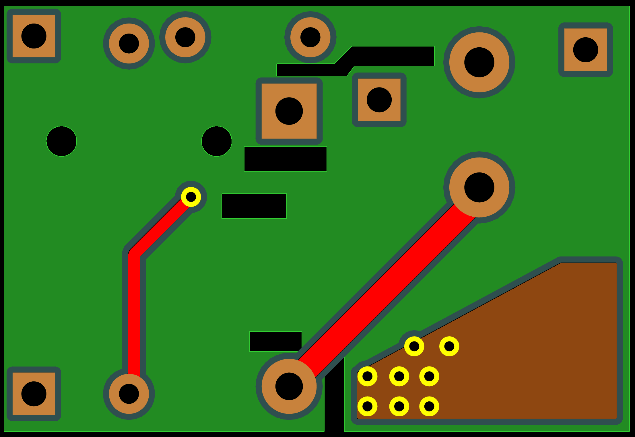
- Compare the calculated isolation paths with the imported copper geometry.
Review checklist
- Every copper feature that requires isolation has a contour.
- Tracks, pads, vias and copper areas have not been narrowed or removed unintentionally.
- Extra passes create a continuous cleared channel without thin copper ridges.
- The expected top and/or bottom layers contain calculated contours.
- Offsets and special Cut Side settings do not conflict with narrow gaps or fine-pitch pads.
If the result is incorrect, adjust the tool, passes, overlap, layer selection, Cut Side or Extra Offset, and select Calculate again.